If you want better control over where grain lands in the cart, the Hillco Pivoting Spout is a practical upgrade for your Case IH combine. From the cab, a foot switch moves the spout through 37 degrees of travel, allowing you to direct the grain stream closer to or farther away from the combine without repositioning the machine.
In this guide, we’ll walk through the main steps for installing the Hillco CPS1410 Pivoting Spout on compatible Case IH combines. It is designed as a helpful overview, so keep the official Hillco installation manual nearby for the complete parts list, wiring diagram, measurements and model-specific details.
Compatibility note:
The CPS1410 manual covers Case IH 50/60/7088, 70/8010 and 71/81/9120 combines. Confirm that you have the correct kit and current manual for your combine before beginning
Park the combine on a firm, level surface, lower the header and unloading auger, shut off the engine, remove the key and follow the combine manufacturer’s lockout and safety procedures. Disconnect electrical power before beginning the wiring portion of the installation.
Because the work takes place at the end of the unloading auger, use a stable ladder, scaffolding, forklift work platform or another safe way to reach the correct working height. A second person can also make it easier to position and support the spout components.
Tools You’ll Need
The official manual includes the complete tool list. The primary tools include:
3/8-inch battery driver
13 mm deep socket, extension and two 13 mm wrenches
Medium or large channel-lock pliers
Needle-nose pliers
Grinder with a cutoff wheel
Wire strippers and electrical crimpers
Heat gun or lighter for heat-shrink connections
Drill and the drill bits listed in the manual
Phillips screwdrivers
Zip ties
Ratchet strap for temporarily supporting the mount
Safe equipment for working at auger height
Before starting, inventory the spout, mounting components, actuator, relay, foot switch, wiring harnesses and labeled bolt bags supplied with the kit.
Step 1: Remove the Factory Spout
Remove the two hose clamps holding the factory spout to the end of the unloading auger, then remove the original spout.
Next, remove the grain dam and save its hardware for reinstallation. The dribble-door bolts will also need to be removed so the existing boot and dribble door can slide off.
Step 2: Modify and Reinstall the Grain Dam
The grain dam must be modified to provide clearance for the new Hillco Pivoting Spout. Using a grinder with a cutoff wheel, remove the section containing the thicker welded steel cross. Make the cut at the edge of the cross while leaving the remaining grain dam as long as possible.
Once the modification is complete, reinstall the grain dam using the original hardware.
Installation tip: Review the manual’s photos closely before cutting. The goal is to remove only the required reinforced section while retaining as much of the original grain dam as possible.
Step 3: Assemble the New Spout and Boot Mount
Locate the polyethylene spout, metal boot mount and Bolt Bag 1. Attach the spout to the metal mount using the supplied M8 x 25 carriage bolts, fender washers and nyloc nuts.
Install the carriage bolts with the bolt heads facing the inside of the spout. Tighten the hardware evenly, taking care not to distort the polyethylene spout.
Step 4: Assemble and Position the Tray Mount
Locate the two mounting straps and the tray mount. Use the four shorter M8 x 16 bolts and nuts from Bolt Bag 2 to fasten the straps to the tray. The bends in the straps should face away from the tray so they are correctly oriented when wrapped around the auger tube.
Position the tray mount approximately 4 5/8 inches back from the bottom end of the auger tube, following the measurement shown in the manual. This dimension may need a slight adjustment depending on the combine model.
Secure the mount around the auger tube with the supplied M8 x 40 bolts and nuts. Longer M8 x 80 bolts are also included for models that require them. Form the straight straps around the tube and use channel-lock pliers to draw the mounting tabs close enough to start the nuts.
A ratchet strap can be used to temporarily hold the tray mount in position while the mounting hardware is installed and tightened.
Step 5: Attach the Pivoting Spout and Actuator
Connect the lower pivot points of the boot mount to the tray mount using the two 1/2 x 1 1/2-inch clevis pins identified in the manual. Secure each pin with a cotter pin.
Next, position the linear actuator as shown in the installation diagram. Attach it to the tray mount and boot mount with the two 1/2 x 2-inch clevis pins, then secure the pins with cotter pins.
Before moving on, confirm that the spout pivots freely and that it is not binding against the mount or hardware.
Step 6: Route the Actuator Harness
Plug the two-conductor harness into the linear actuator and route it along the unloading auger toward the battery area. Secure the harness with the supplied zip ties and follow existing machine harnesses where practical.
Pay close attention at the unloading-auger pivot. Leave enough slack for the auger to rotate through its full range, but not so much that the wire can contact belts, gears or other moving components.
Do not cut the harness or make the final connections until the relay location has been selected.
Step 7: Install the Foot Switch
Inside the cab, lift the floor mat to the left of the steering column and identify a suitable pass-through for the foot-switch harness. If an existing pass-through is not available, drill the correct-size hole for the supplied strain relief, following the measurements in the manual.
If a new opening is needed, place it in a valley in the cab floor so the harness does not cause the floor mat to sit unevenly.
Pass the harness through the strain relief, connect it to the foot switch and mount the switch where it can be comfortably operated with the operator’s left foot. Route the remaining harness toward the battery area alongside existing wiring. Leave the harness loose until the relay connections are complete, then coil and secure any excess away from heat, sharp edges and moving parts.
Step 8: Mount and Wire the Relay
Choose a protected mounting location near the battery box. The exact location may vary by combine model. Using the relay as a template, mark and drill the mounting holes, then install the relay with its terminals facing down to help protect the connections.
Connect the foot-switch and actuator harnesses to the relay exactly as shown in the Hillco wiring diagram. Then connect the power harness:
Orange fused wire to the positive terminal on the controller
Black wire to the negative terminal on the controller
Power and ground leads to the appropriate 12-volt battery connections
The 20-amp fuse must be installed as close to the battery or power source as possible—within the first eight inches of wire, according to the manual.
Because an incorrect connection can damage components or cause the spout to operate in the wrong direction, use the official wiring diagram rather than wire color alone when making the final connections.
Step 9: Test the Pivoting Spout
Reconnect power and test the system from the cab. Press the UP side of the foot switch to direct the grain stream farther away from the combine, and press DOWN to bring the stream closer.
Cycle the unloading auger through its normal range and watch the harness near the auger pivot. Confirm that the wiring has enough slack to move freely without pulling tight, becoming pinched or contacting moving parts.
The spout should travel smoothly without binding. Release the foot switch when the spout reaches the desired position or the end of its travel. Holding the switch after the actuator reaches its limit will cause the actuator to ratchet, which can shorten component life and may blow the fuse.
Troubleshooting at a Glance
The spout does not move
Check the 20-amp fuse and replace it if necessary.
Inspect the wiring and relay connections.
Make sure the spout is not caught or binding on mounting hardware.
Avoid resting a foot on the switch, which can hold the actuator at its limit and blow the fuse.
The spout moves in the wrong direction
Reverse the actuator wires at the relay or reverse the black and green foot-switch wires as directed in the manual.
The spout moves in only one direction
Use the diagnostic procedure in the manual to determine whether the problem is in the relay circuit or the foot switch. If the switch wiring or internal connections need repair, follow the detailed foot-switch instructions or contact Hillco Product Support.
Ready for More Control at Unloading?
Once installed, the Hillco Pivoting Spout gives the operator precise, foot-controlled adjustment of the grain stream from inside the cab. That added control can make it easier to top off the grain cart, compensate for changing wind or field conditions and reduce grain spilled during unloading.
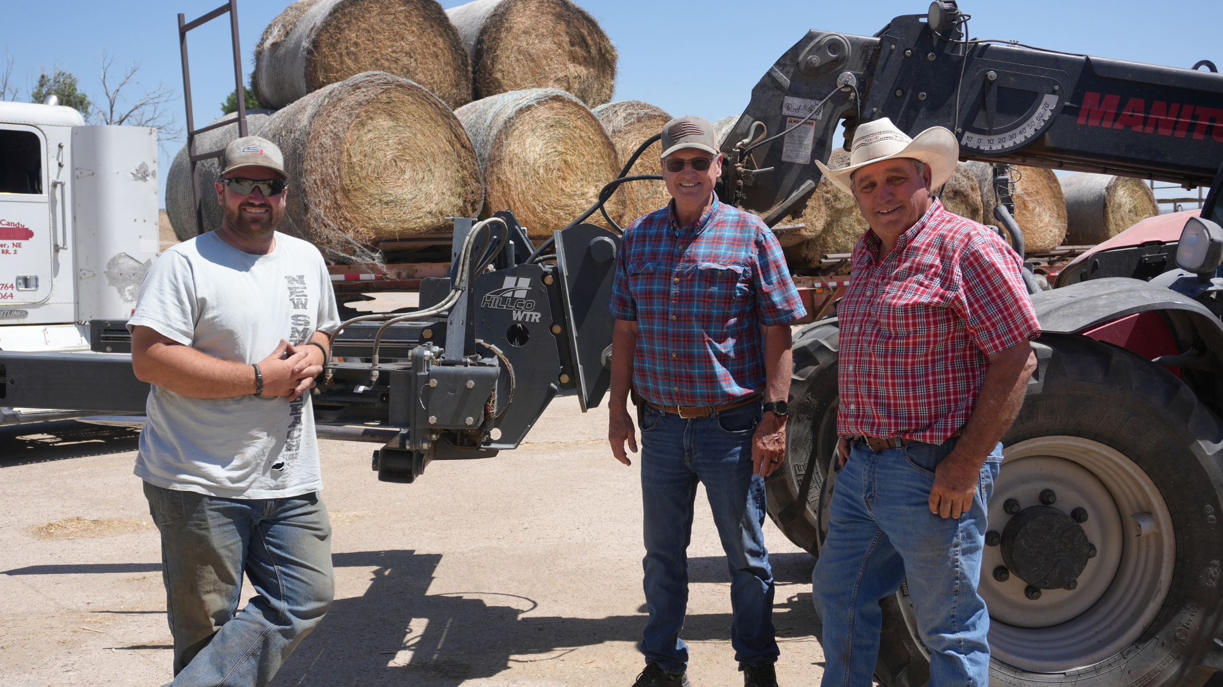
Quick Answer: Cutting the net wrap or twine off one bale isn’t something a person thinks much about, but a few hundred bales—that’ll get your attention. At Oshkosh Heifer Development in western Nebraska, experienced hay-grinding professionals Marty Zehr and Tyler Schroeder have put the Hillco Wrap Twine Remover through an extreme-use workload, cutting and collecting net wrap and twine while handling the bale—without crawling in and out of the cab upwards of 400 times a day.
Hear directly from Hillco customers at Christensen and Millhorn Farms about the knowledgeable field support, equipment adjustments and personal service they experienced when it mattered most.
Enter your farm data to calculate what a Hillco leveling system puts back in your pocket. Fields are pre-filled with study data — update the numbers that apply to your operation.
🌿 Acreage & Crop Information
🌽 Corn
Total acres
Avg yield (bu/ac)
Price ($/bu)
🌱 Soybeans
Total acres
Avg yield (bu/ac)
Price ($/bu)
🌾 Wheat optional
Total acres
Avg yield (bu/ac)
Price ($/bu)
% of total acres per slope range — all crops combined (must total 100%)
0–3% slope
4–9% slope
10–15% slope
16%+ slope
⚠ Slope percentages must add up to 100%
⚙ Harvest Speeds (MPH) — Without Leveling System
With a Hillco leveling system, your combine harvests slopes at your flat-ground (0–3%) speed.
Slope
Corn
Soybeans
Wheat
0–3%
4–9%
10–15%
16%+
🌿 Reduction in Machine Harvested Yield (bu/acre)
Enter your estimated reduction in harvested yield (bu/acre) for each slope range when operating at your flat-ground speed (0–3% slope). The calculator will adjust these values based on the ground speeds entered for each slope range. Hillco study data is pre-filled and may be overridden with your own estimates.
Slope
Corn
Soybeans
Wheat
0–3%
4–9%
10–15%
16%+
🚜 Combine & Header Information
Corn head width (ft)
Flex header — soybeans (ft)
Wheat platform width (ft)
Field efficiency (%)
Typically 70% (separator hrs ÷ engine hrs)
Cost per separator hour ($)
$300–$400 new, ~$150 older. Enter $0 to exclude.
💵 Operational Costs
Operator labor ($/hr)
Fuel price ($/gal)
Fuel consumption (GPH)
Typically 16–20 GPH
📈 Leveling System Investment
John Deere S7 Sidehill (18%): ~$84,000 | John Deere S7 Hillside (28%) w/ dual tire: ~$155,400 | Case IH Flagship Sidehill: ~$82,000 | Case IH Flagship Hillside w/ dual tire: ~$152,500. Consult your dealer for used values.
List price of leveling system ($)
Market value after year 5 ($)
Hillco systems retain ~40% of original value after 5 years
Annual interest rate (%)
Calculation period (1–5 yrs)
Annual inflation rate (%)
Your Hillco Leveling System ROI
$0
total net cash flow over your selected period
0.0 yrs
Estimated payback period
$0
Grain savings (total period)
$0
Labor + fuel savings
$0
Combine resale value gain
Annual separator hours
0
Without leveler
0
With leveler
0
Hours saved/yr
0%
% savings
Payback progress (5-year window)
Payback: calculating...
Cash Flow Breakdown — 5 Years
Grain savings (reduced MHY losses)$0
Labor savings$0
Fuel & lubrication savings$0
Residual value of leveling system$0
Increased combine resale value$0
Total positive cash flows$0
Leveling system cost (principal + interest)$0
Remaining note balance (if period < 5 yrs)$0
Maintenance cost (2%/yr after year 1)$0
Total negative cash flows$0
Net cash flow$0
$0
Net present value (NPV)
0%
Internal rate of return (IRR)
Results are estimates based on your inputs and Hillco study data. Actual results may vary. Contact your local Hillco dealer for a personalized quote | 1-800-937-2461 | hillcotechnologies.com
Proudly American Made
2026 Hillco Technologies, Inc. All Rights Reserved.